
Light and Reflaction
Light: – The medium through which we can see any object with the help of eyes is called light.
OR
Light is a form of energy which induces the sensation of vision in our eyes.
Question: – Why do we see the object?
When light falls on an object, some of the light gets reflected. The reflected light comes to our eyes and we are able to see an object.
Important facts related to light
* It travels in straight line.
* Light can form shadows.
* Light is an electromagnetic wave which can travels without any medium.
* Light is the form of energy. The main source of light is sun.
* The range of wavelength of visible light is 400-700 nanometres (nm). Or 4×10⁻⁷to 7×10⁻⁷m
* The velocity of light is 3×10⁵ Km/sec Or 3×10⁸ m/sec
* The distance of earth from sun is 1.5×10⁸ Km = 15×107 Km
* The sun light reaches on earth in 8 minutes 20 Seconds.
* Mass of earth= 5.972 × 1024 Kg
* The light always travels on a straight line. This phenomenon is called rectilinear propagation of light
REFLECTION OF LIGHT
The bouncing back of rays of light from a polished and shiny surface is called reflection or reflection of light.
|
|
Note- A highly polished surface, such as a mirror, reflects most of the light falling on it.
Similarly, Shiny/smooth surfaces reflects more light whereas dull/rough surfaces reflects less light
Plain Mirror- A mirror having flat reflected surface is plane mirror.
* Mirror surface is polish by a very thin layer of silver bromide (AgBr2).
Some mirrors have the silvering at the back like the ones used by us (normal use)

The way the light reflects is shown in the following diagram. (It is usual to show the shiny surface by a line and the back of the mirror by a shaded section).

General terms related to plane mirrors:
Incident ray (Apatit kiran):-The ray of light that strikes on the surface is called incident ray. (Labelled I in the diagram).
Reflected ray (paravartit kiran):-The ray of light that goes back after reflection is reflected ray (Labelled R in the diagram).
Point of incident (aapatan bindu):- The point on which the incident ray strikes are called point of incident. (Labelled O in the diagram)
Normal (abhilamb):- The line drawn perpendicular on point of incident is called normal line (labeled N in the diagram).
The normal line divides the angle between the incident ray and the reflected ray into two equal angles.
Angle of incident: – The angle between the incident ray and the normal is called angle of incidence. In fig
Angle of reflection: – The angle between the reflected ray and the normal is called the angle of reflection. In fig
Laws of REflection of Light:
The two laws of reflection are:
i. The angle of incidence is equal to the angle of reflection,
ii. The incident ray, the normal to the mirror at the point of incidence and the reflected ray, all lie in the same plane.
These laws of reflection are applicable to all types of reflecting surfaces including spherical surfaces.
Types of reflection
1. Regular reflection
2. Diffused reflection:
Regular reflection: The reflection in which all reflected rays are parallel to each is called regular reflection.
Ex:- Reflection by a mirror, reflection from still water etc
* It occurs on smooth and well-polished surface.
Diffused reflection: The reflection in which all reflected rays are not parallel to each is called diffused reflection.
Ex- reflection of light from the wall of a room or tree etc
* It occurs on rough surface.
|
|
Formation of image by plane mirror:
The light rays from the object spread out, hit the mirror and then reflect – they seem to have come from a point behind the mirror. This is the image of the object. Image is denoted as ‘I’
Light rays from an object hit the mirror after reflection they appear to meet at (I). Image is seen at I
* Image is formed behind the mirror
* Distance of object from mirror = Distance of image from the mirror.
OR Distance of object and image is the same from the mirror. (Shown as distance ‘d’ in fig shown above)
Image of extended object in plain mirror:
An extended object AB is placed in front of a plane mirror MM1. From the points A and B of the object, rays of light travel in all directions.
Two rays (AP and AQ) starting from A, incident on the mirror gets reflected as PP‘ and QQ‘ respectively from the mirror.
These reflected rays when produced backwards meet at the point A‘. In other words, for an observer these reflected rays appear to come at A‘ . Thus A‘ is the virtual image of the point A.
In the same way, two rays (BR and BS) starting from B, incident on the mirror gets reflected as RR‘ and SS‘ respectively from the mirror.
Thus, B ‘is the virtual image of the point B.
Thus A‘B‘ is the virtual image of the object AB. It is erect and of size equal to that of the object. It is formed far behind the plane mirror as the object is in front of it. i.e., the distance of object and image is the same from the mirror
Lateral inversion:
“Lateral inversion” means the apparent reversal of the mirror image’s left and right when compared with the object.
* In other words, when an object is placed in front of the plane mirror, sides are reversed. Right becomes left and left becomes right. This reversal is only in the direction perpendicular to the surface of the mirror.
Ex- the word AMBULANCE is painted left-right inverted on the ambulance so that when the driver of a vehicle in front looks into his rear-view mirror, he can make out the word AMBULANCE quickly and give way.
Object: Something from which light rays start is called object. The light rays may be the self or reflected rays of object(i.e., they can either be luminous or non-luminous)
Image: Image is the point where light rays meet or appear to meet.
Image can be of two types:
1. Real image(वास्तविक प्रतिबिम्ब)
A real image occurs where rays converge, i.e., light rays actually meet at image. They can be projected on screen
2. Virtual image(काल्पनिक प्रतिबिम्ब)–
virtual image occurs where rays only appear to converge,.i.e., light rays appear to meet at image. They cannot be projected on screen
Property of image formed by plane mirror:
i) Image is virtual and cannot be projected on screen
ii) Image is erect
iii) Image is of the same size as the object
iv) Laterally inverted
v) Distance of image and object from the plane mirror is same
Uses of plane mirror
* To see ourselves
* To make some instruments like periscope
* In shops for decoration
For light rays striking a plane mirror, the angle of reflection equals the angle of incidence.
Spherical mirrors:
The mirrors, whose reflecting surfaces are spherical, are called spherical mirrors.
* It is made from a part of the surface of a transparent sphere.
* The one surface of it is polished.
* The reflecting surface of a spherical mirror may be curved inwards or outwards.
Types of Spherical Mirror:
i) Concave mirror– A spherical mirror whose outer surface is polished and inner side is the reflecting surface is called concave mirror.
* A concave mirror is also called converging mirror as it converges the incident rays after reflection.
ii) Convex mirror– A spherical mirror whose inner is polished and outer side is the reflecting surface is called convex mirror.
* A convex mirror is also called diverging mirror as it diverges the incident rays after reflection.
Note- Laws of reflection are applicable to all types of mirrors.
Important terms in the case of spherical mirror:

i) Pole(ध्रुव): The centre of reflecting surface of a spherical mirror is called Pole.
* Pole lies on the surface of spherical mirror.
* Pole is generally represented by ‘P’. The middle point of the mirror is called pole of the mirror.
ii) Centre of Curvature(वक्रता केंद्र): The reflecting surface of a spherical mirror forms a part of a sphere. This sphere has a centre. This point is called the centre of curvature of the spherical mirror.
* It is represented by the letter C.
* In the case of concave mirror centre of curvature lies in front of the reflecting surface.
* On the other hand, centre of curvature lies behind the reflecting surface in the case of convex mirror.
iii) Radius of Curvature(वक्रता त्रिज्या): The radius of sphere of which the reflecting surface of a spherical mirror is a part is called the Radius of Curvature of the spherical mirror.
* The radius of curvature of a spherical mirror is denoted by letter ‘R’.
* Similar to centre of curvature, radius of curvature lies in front of concave mirror.
* lies behind the convex mirror and is not a part of the mirror as it lies outside the mirror.
iv) Aperture(द्वारक): The diameter of reflecting surface of a spherical mirror is called aperture.
(shown as MM’.i.e., vertical line joining M and M’)
v)Principal Axis(प्रधान अक्ष): Imaginary line passing through the centre of curvature and pole of a spherical mirror is called the Principal Axis.
vi)Focus or Principal Focus(फोकस): Point on principal axis at which parallel rays coming from infinity converge after reflection is called the Focus or Principal Focus of the spherical mirror. Focus is represented by letter ‘F’.
Focal plane– The plane through the focus perpendicular to the axis of a mirror or lens. In other words, the vertical plane in which the focal point lies is the focal plane
If parallel rays traveling toward a converging mirror are not parallel to the main axis, they still come to a point after reflection, but not at the main focal point F. We can visualize a plane that passes through F and is perpendicular to the main axis, as shown. It is called the “focal plane.” Parallel rays that are not parallel to the main axis gather at a point (such as F1)on the focal plane.
|
|
In the case of a diverging (convex) mirror, rays reflect in a manner that they appear to have come from a point on the virtual focal plane
|
|
A concave mirror can be used to focus light of the sun to burn a hole in paper. The light from the Sun is converged at a point, as a sharp, bright spot by the mirror. This spot of light is the image of the Sun on the sheet of paper. This point is the focus of the concave mirror. The heat produced due to the concentration of sunlight ignites the paper. The distance of this image from the position of the mirror gives the approximate value of focal length of the mirror
Rays parallel to principal axis meet at focus on reflection from concave mirror.
In the case of a concave mirror, parallel rays coming from infinity converge after reflection in front of the mirror. Thus, the focus lies in front of a concave mirror.
Fig: Converging Mirror(concave)
Rays parallel to principal axis meet at focus on extending on reflection from convex mirror.
In the case of a convex mirror, parallel rays coming from infinity appear to be diverging from behind the mirror. Thus, the focus lies behind the convex mirror.
Fig: Diverging Mirror(convex)
vii)Focal length: The distance from pole to focus is called focal length. Focal length is denoted by letter ‘f’. Focal length is equal to half of the radius of curvature.
Image Formation by Spherical Mirrors
Representation of Images Formed by Spherical Mirrors Using Ray Diagrams
The different ways in which a ray of light is reflected from a spherical mirror are:
Case I:
Reflection of Rays parallel to Principal Axis:
In the case of concave mirror: A ray parallel to principal axis passes through the principal focus after reflection from a concave mirror.
Similarly, all parallel rays to the principal axis pass through the principal focus after reflection from a concave mirror. Since, a concave mirror converge the parallel rays after reflection, thus a concave mirror is also called converging mirror.

In the case of convex mirror: A ray parallel to principal axis appears to diverge from the principal focus after reflecting from the surface of a convex mirror.
Similarly, all rays parallel to the principal axis of a convex mirror appear to diverge or coming from principal focus after reflection from a convex mirror. Since, a convex mirror diverges the parallel rays after reflection, thus it is also called diverging mirror.
Case 2
Reflection of ray passing through the Principal Focus:
In the case of concave mirror: Ray passing through the principal focus goes parallel to principal axis after reflection in the case of concave mirror.
Fig: Ray passing through principal focus
In the case of convex mirror: A ray directed towards principal focus goes parallel to principal axis after reflecting from the surface of a convex mirror.
Fig: Ray through principal focus
Case 3:
Ray passing through the Centre of curvature:
A ray passing through the centre of curvature of a concave mirror or directed in the direction of the centre of curvature of a convex mirror, after reflection, is reflected back along the same path. The light rays come back along the same path because the incident rays fall on the mirror along the normal to the reflecting surface
Case 4
Ray incident obliquely to the principal axis: Ray obliquely to the principal axis goes obliquely after reflecting from the pole of the both concave and convex mirror and at the same angle.
- A ray incident obliquely to the principal axis, towards a point P (pole of the mirror), on the concave mirror [Fig. (a)] or a convex mirror [Fig. (b)], is reflected obliquely. The incident and reflected rays follow the laws of reflection at the point of incidence (point P), making equal angles with the principal axis.

In all the above cases, the laws of reflection are followed. At the point of incidence, the incident ray is reflected in such a way that the angle of reflection equals the angle of incidence.
Want to learn by Video Lectures? CLICK HERE to watch them
Ray diagrams for the formation of image by a concave mirror for various positions of the object are-
i) Object between Principal Focus (F) and Pole (P):
When the object is placed between principal focus and pole of a concave mirror, an enlarged, virtual and erect image is formed behind the mirror.
Properties of image:
ii)Object at Principal Focus (F):
When the object is placed at principal focus (F) of a concave mirror, a highly enlarged image is formed at infinity.
Properties of image:
iii)Object between Centre of curvature (C) and Principal Focus (F):
When the object is placed between centre of curvature and principal focus of concave mirror, a real image is formed beyond the centre of curvature (C).
Properties of image:
iv)Object at Centre of Curvature (C):
When the object is placed at centre of curvature (C) of a concave mirror, a real and inverted image is formed at the same position.
Properties of image:
v)Object between infinity and centre of curvature:
When object is placed between infinity and centre of curvature of a concave mirror the image is formed between centre of curvature (C) and focus (F).
Properties of image:
vi)Object at infinity:
Since parallel rays coming from the object converge at principal focus, F of a concave mirror after reflection. Hence, when the object is at infinity the image will form at F.
Properties of image:
|
Position of the object |
Position of the image |
Size of the image |
Nature of the image |
|
At infinity |
At the focus F |
Highly diminished, point sized |
Real and inverted |
|
Beyond C |
Between F and C |
Diminished |
Real and inverted |
|
At C |
At C |
Same size |
Real and inverted |
|
Between C and F |
Beyond C |
Enlarged |
Real and inverted |
|
At F |
At infinity |
Highly enlarged |
Real and inverted |
|
Between P and F |
Behind the mirror |
Enlarged |
Virtual and erect |
The ray diagrams the image formation by a convex mirror for different positions of the object
There are only two possibilities of position of object in the case of a convex mirror, i.e. object at infinity and object between infinity and pole of a convex mirror.
i)Object at infinity: When the object is at the infinity, a point sized image is formed at principal focus behind the convex mirror.
Properties of image: Image is highly diminished, virtual and erect.
ii) Object between infinity and pole: When the object is between infinity and pole of a convex mirror, a diminished, virtual and erect image is formed between pole and focus behind the mirror.
Properties of image: Image is diminished, virtual and erect.
|
Position and Nature of Image in Convex Mirror |
|||
|
Position of object |
Position of image |
Size of image |
Nature of image |
|
At infinity |
At F, behind mirror |
Highly diminished |
Virtual and Erect |
|
Between infinity and pole |
Between F and P, behind mirror |
Diminished |
Virtual and Erect |
Distinguishing between the 3 types of mirrors
When we stand in front of the mirror, then the image
- Plane mirror- Will be of the same size as object
- Concave mirror- Larger than the object
- Convex mirror- Will be smaller than the object
Uses of concave mirror:
Uses of convex mirrors
Mirror Formula and Magnification
A formula which provides a relation between image distance(v), object distance(u), and focal length(f) of a spherical mirror is called Mirror formula.
Mirror formula:
Where v = distance of image from the mirror
u = distance of object from the mirror
f= focal length of the mirror.
Want to learn by Video Lectures? CLICK HERE to watch them
Sign Convention for Reflection by Spherical Mirrors
Reflection of light by spherical mirrors follow a set of sign conventions called the New Cartesian Sign Convention. In this convention, the pole(P) of the mirror is taken as the origin. The principal axis of the mirror is taken as the X-axis(X’X) of the coordinate system.
The conventions for spherical mirrors are as follows-

Magnification
Magnification is the ratio of the height of the image to the height of the object. It is usually represented by the letter ‘m’.
Relation among magnification, distance of object and distance of image:
Where, m = magnification, h’ = height of image, h = height of object, v = image distance and u = object distance.
Magnification produced by a spherical mirror gives the relative extent to which the image of an object is magnified with respect to the object size. The height of the object is taken to be positive as the object is usually placed above the principal axis. The height of the image should be taken as positive for virtual images and as negative for real images.
A negative sign in the value of the magnification indicates that the image is real. A positive sign in the value of the magnification indicates that the image is virtual.
REFRACTION OF LIGHT
Three different things happen when light hits a surface, it can be reflected (bounce off), absorbed or transmitted (pass through).
Substances which transmit most of the light and only absorb or reflect a little bit are called transparent.
Substances which completely reflect or absorb light without transmitting any are called opaque.
Some substances, such as the plastic shopping bag, allow some light to pass through, but not all of it. This substance is translucent, or semi-transparent.
Opaque Objects
Objects through which we cannot see anything are called opaque objects. A medium that does not allow light to pass through it is called an opaque medium. Examples of opaque objects are wood, stone, and metals(iron). Most objects in our surroundings, like buildings and trees, are opaque objects.
Transparent Objects
Objects through which we can see clearly are called transparent objects. A medium that allows all the light incident on it to pass through it is called a transparent medium. Examples of transparent objects are pure water, kerosene, turpentine. Glass, Ex-, is transparent to all visible light.
Translucent Objects
Objects through which we cannot see the objects on the other side clearly but can see some light are called translucent objects. A medium that allows only a part of the light incident on it to pass through it is called a translucent medium. Examples of translucent objects are ground glass, frosted glass, smoked glass, sun glasses and butter paper. and some plastics
Refraction is a phenomenon of bending of light when it travels from one medium to another.
The refraction of light takes place on going from one medium to another because the speed of light is different in two media.
Speed of light:
In vacuum= 3 x10⁸m/s
In air= Slightly less than the speed of light in vacuum.
Light travels with different speed in different medium. It travels fastest in vacuum.
The Refractive Index
It is denoted as ‘n’
Refractive Index is the extent of change of direction of light in a given pair of media. The refractive index is a relative value of speed of light in the given pair of media.

Thus, to calculate the refractive Index the speed of light in two media is taken.
Let the speed of light in medium 1 is v1 and in medium 2 is v2
Therefore,
Above expression gives the refractive index of medium 2 with respect to medium 1. This is generally denoted by n21.
Similarly, the refractive index of medium 1 with respect to medium 2 is denoted by n12.
Absolute Refractive Index:- When one medium is taken as vacuum and speed of light is taken in it, then the refractive index of second medium with respect to vacuum is called Absolute Refractive Index and it is generally denoted by n2. The absolute refractive index of a medium is simply called its refractive index.
The speed of light in vacuum is slightly faster than in air.
Let speed of light in air is ‘c’ and the speed of light in given medium is ‘v’.
Therefore,
Absolute refractive index of some material media
|
Material medium |
Refractive index |
Material medium |
Refractive index |
|
Air |
1.0003 |
Canada Balsam |
1.53 |
|
Ice Water Alcohol |
1.31 1.33 1.36 |
Rock salt |
1.54 |
|
Kerosene |
1.44 |
Carbon disulphide |
1.63 |
|
Fused quartz |
1.46 |
Dense flint glass |
1.65 |
|
Turpentine Oil |
1.47 |
Ruby |
1.71 |
|
Benzene |
1.50 |
Sapphire |
1.77 |
|
Crown glass |
1.52 |
Diamond |
2.42 |
Optically denser medium and optically rarer medium:
Optical dense refers to the index of refraction. If one medium is optically denser than another, then its index of refraction is larger, meaning the speed of light in the optically denser medium is smaller.
Optically denser medium: A medium in which light travels comparatively slower than the other medium is called optically denser medium. E.g. water
Optically rarer medium: A medium in which light travels comparatively faster than the other medium is called optically denser medium. E.g. Air
Consider two liquids namely alcohol and kerosene. The refractive index of kerosene(1.44) is more than that of alcohol(1.36).
Then we say kerosene is optically denser n alcohol is optically rarer. The more dense the medium, the slower the light moves.
Similarly, when we compare water and kerosene, kerosene is optically denser(1.44) than water(1.33). But, the mass density of kerosene is less than that of water.
In other words, there is no relation between optical density and mass density.
Optical Density–is an inverse measure of the speed of light through the medium.
As the refractive index of a substance decreases the speed of light in that particular medium is more. Ex-, refractive index of water is 1.33 but that of turpentine is 1.47. Therefore, light travels faster in water than in turpentine.
Refractive index of medium 1 with respect to medium 2(n12)=
=Speed of light in medium2/speed of light in medium 1=v2/v1
Similarly,
Refractive index of medium 2 with respect to medium 1(n21)=
=Speed of light in medium1/speed of light in medium 1
=v1/v2
In other words, n12= 1/n21
Want to learn by Video Lectures? CLICK HERE to watch them
Laws of refraction of light:

- The incident ray, the refracted ray and the normal to the interface of two transparent media at the point of incidence, all lie in the same plane.
- The ratio of sine of angle of incidence to the sine of angle of refraction is a constant, for the light of a given colour and for the given pair of media. This law is also called Snell’s law of refraction. If i is the angle of incidence and r is the angle of refraction, then,
sin i / sin r = n21=constant
This constant value is called the refractive index of the second medium with respect to the first.
Bending of light
- If light moves from a less dense medium, like air, into a denser medium, like glass, then the light slows down. The light will bend towards the normal line.

- If light moves from a denser medium to a less dense medium then the light speeds up and moves away from the normal.

If light ray is incident perpendicularly to an interface, it does not bend.
Refraction through a Glass Slab
Air refractive index=1 and that of water
Light ray comes from rarer to denser medium. Therefore, it moves towards normal. Then it moves out of the glass slab into air. Here light rays, moves from denser to rarer medium. Therefore, it moves away from the normal.
Light passing through the glass slab encounters refraction two times once at air to glass interface and other at glass to air interface. Following are the features:
Angle of incidence and angle of emergence are equal as emergent ray and incident ray are parallel to each other.
Effects of refraction of light:
- Bending of pencil when placed in a glass with water:

When a pencil or stick is kept in a beaker or a glass filled with water, the stick appears slightly bent. This happens because the light entering from air (rarer medium) into water (denser medium); bends towards normal to the incident which makes the appearance of pencil or stick as bent.
- An object placed under water appears to be raised: The ray coming from the coin in the bowl bends away from the normal to the incident. We see the emergent ray which makes the appearance of coin slightly above its position.

c)A pool of water appears to be less deep than it is actually is : The refraction of light at the surface of water makes ponds and swimming pools appear shallower than they really are.

d) Letters beneath slab seems to be raised due to refraction
Want to learn by Video Lectures? CLICK HERE to watch them
Refraction by spherical lens:
What is a lens?
Lens is a transparent material bound by two surfaces, of which either both spherical or one spherical and other plane.
Types of lenses:
i)Convex lens: A lens that has two spherical surfaces, bulging outwards is called a double convex lens. It is simply called a convex lens. These lenses are thicker at the centre and thinner at the ends. These are also called converging lens as these lenses converges the light rays falling on them.
ii)Concave Lens: A lens that is bounded by two spherical surfaces, curved inwards is called a double concave lens. A double concave lens is simply called a concave lens. These lenses are thinner in the middle and thicker at the ends. These are also called diverging lens as the light falling on these lenses gets diverged.
Important terms in the case of spherical lenses:
(a) Focal Length:- The distance between optical centre and principal focus is called focal length of a lens.
Focal length of a lens is half of the radius of curvature.
This is the cause that the centre of curvature is generally denoted by 2F for a lens instead of C
(b) Centre of curvature:
Centre of curvature: A lens, either a convex lens or a concave lens, has two spherical surfaces. Each of these surfaces forms a part of a sphere. The centres of these spheres are called centres of curvature of the lens. The centre of curvature of a lens is usually represented by the letter C. Since concave and convex lenses are formed by the combination of two parts of spheres, therefore they have two centres of curvature.
One centre of curvature is usually denoted by C1 and second is denoted by C2.
( c) Radius of curvature: The distance between optical centre and centre of curvature is called the radius of curvature, which is generally denoted by R.
(d)Principal Axis: An imaginary straight line that passes through the centres of curvature of a lens is called Principal axis.
(e) Optical centre: The central point of a lens is called its Optical Centre. A ray passes through optical centre of a lens without any deviation.
(f) Aperture: The effective diameter of the circular outline of a spherical lens is called its aperture.
(g) Principle focus:-
(i) Concave Lens :- The principle focus of a concave lens is a point on its principle axis from which light rays, originally parallel to the axis, appears to diverge after passing through the lens has a virtual focus represented by letter F’
(ii) Convex Lens :- The principle focus of a convex lens is a point on its principle axis to which light rays originally parallel to the principle axis converge after passing through it. A convex lens has a real focus represented by letter f.
Image Formation by Lenses
The rules for image formation in lenses are-
• A ray passing through the optical centre (O) of the lens proceeds undeviated through the lens.

• A ray passing parallel to the principal axis after refraction through the lens passes or appears to pass through the focus(F). (By definition of the focus)

• A ray through the focus or directed towards the focus(F’), after refraction from the lens, becomes parallel to the principal axis. (Principal of reversibility of light)

Image formation by convex lens by placing objects in the following positions:
- Object between principal focus, F and optical centre, O
- Object at principal focus, F
- Object between centre of curvature, C and principal focus, F
- Object at centre of curvature, C
- Object beyond centre of curvature, C
- Object at infinity
(a) Between principal focus, F1 and optical centre, O:-
A virtual, erect and enlarged image is formed at the same side of lens, when an object is placed between principal focus, F1 and optical centre, O of a convex lens.
Position of image: Beyond 2F1
Nature of image: Virtual and erect
Size of image: Enlarged.
b) Object at principal focus, F1:-
An infinitely large, real and inverted image is formed at infinity when object is placed at principal focus, F1 of a convex lens.
Position of image: At infinity
Nature of image: Real and inverted
Size of image: Highly enlarged
c) Object between centre of curvature, C1 and principal focus, F1:
An enlarged, real and inverted image is formed beyond centre of curvature, C2 when an object is placed between centre of curvature, C1 and principal focus, F1 of a convex lens.
Position of image: Beyond 2F2
Nature of image: Real and inverted
Size of image: Enlarged
d) Object at centre of curvature, C1 or 2F1:
A same sized, real and inverted image is formed at centre of curvature, C2 when object is placed at centre of curvature, C1 of a convex lens.
Position of image: At 2F2
Nature of image: Real and inverted
Size of image: Same sized.
e) Object beyond centre of curvature, C1 or 2F1:-
A diminished, real and inverted image is formed between principal focus, F2 and centre of curvature, C2 at the opposite side when an object is placed beyond C1 of a convex lens.
Position of image: Between 2F2 and F2
Nature of image: Real and inverted
Size of image: Diminished.
f)Object at infinity:-
Convex lens converge parallel rays coming from objet at infinity and a highly diminished – point sized, real and inverted image is formed at principal focus F2.
Position of image: At F2
Nature of image: Real and inverted
Size of image: Point sized, highly diminished.
Want to learn by Video Lectures? CLICK HERE to watch them
Rules for image formation by converging lenses.
|
Position of the object |
Position of the image |
Relative size of the image |
Nature of the image |
|
At infinity |
At focus F2 |
Highly diminished, point-sized |
Real and inverted |
|
Beyond 2F1 |
Between F2 and 2F2 |
Diminished |
Real and inverted |
|
At 2F1 |
At 2F2 |
Same size |
Real and inverted |
|
Between F1 and 2F1 |
Beyond 2F2 |
Enlarged |
Real and inverted |
|
At focus F1 |
At infinity |
Infinitely large or highly enlarged |
Real and inverted |
|
Between focus F1and optical centre O |
On the same side of the lens as the object |
Enlarged |
Virtual and erect |
The image formation by concave lens by placing the objects in the following positions:
(a) Object is between optical centre, O and infinity
(b) Object is at infinity
(a) Object is between optical centre, O and infinity:
A diminished, virtual and erect image is formed between principal focus F1 and optical centre, O; when object is placed between optical centre and infinity of a concave lens.
Position of image:- Between F1 and O
Nature of image:- Virtual and erect
Size of image:- Diminished.
b)Object is at infinity:-
A highly diminished point sized, virtual and erect image is formed when object is at infinity by a concave lens at principal focus F1.
Position of image:- At F1
Nature of image: Virtual and erect
Size of image: Point sized, highly diminished.
Rules for image formation by diverging lenses.
|
Position of the object |
Position of the image |
Relative size of the image |
Nature of the image |
|
At infinity |
At focus F1 |
Highly diminished, point-sized |
Virtual and erect |
|
Between infinity and optical centre O of the lens |
Between focus F1 and optical centre O |
Diminished |
Virtual and erect |
Sign convention for lens:-
Sign convention for lens is similar to that of spherical mirror.
Signs are taken left of the optical centre as negative, right of the optical centre as positive, above of the principal axis as positive and below of the principal axis as negative.
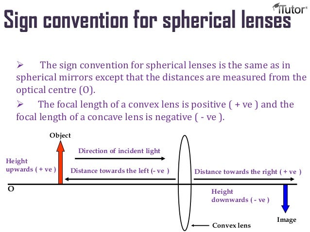
i)All distances on the principal axis are measured from the optical center.
The distances measured in the direction of incident rays are positive and all the distances measured in the direction opposite to that of the incident rays are negative.
All distances measured above the principal axis are positive. Thus, height of an object and that of an erect image are positive and all distances measured below the principal axis are negative.
ii)The focal length of a convex lens is positive and the focal length of a concave lens is negative.
The new sign convention is called New Cartesian Sign Convention. In this, sign is taken negative towards left and taken as positive towards right at X-axis from origin.
Practical application
- Used in spectacles, camera, telescope, microscope etc
Lens Formula and Magnification:
The relation between distance of object, distance of image and focal length for a lens is called lens formula.
Where, v is the distance of image, u is the distance of object, and f is the focal length of lens. Distance of object and image is measure from the optical centre of the lens. The sign for distance is given as per convention.
The lens formula is valid for all situations for spherical lens. By knowing any of the two the third can be calculated.
Magnification:
The ratio of height of image and that of object or ratio of distance of image and distance of object gives magnification. It is generally denoted by ‘m’. If h is the height of the object and h′ is the height of the image given by a lens, then the magnification produced by the lens is given by,
Magnification produced by a lens is also related to the object-distance u, and the image-distance v. This relationship is given by Magnification (m ) = h′/h = v/u
The positive (+) sign of magnification shows that image is erect and virtual while a negative (-) sign of magnification shows that image is real and inverted. A magnification of 2 means the image is twice the size of the object and a magnification of 1 indicates an image size being the same as the object size.
Power of a Lens
The degree of divergence or convergence of ray of light by a lens is expressed in terms of the power of lens. Degree of convergence and divergence depends upon the focal length of a lens. The power of a lens is denoted by ‘P’. The power of a lens is reciprocal of the focal length.
P=1/f
The SI unit of Power of lens is dioptre and it is denoted by ‘D’.
Power of a lens is expressed in dioptre when the focal length is expressed in metre. Thus, a lens having 1 metre of focal length has power equal to 1 dipotre.
A convex lens has power in positive and a concave lens has power in negative.
Want to